Porsche 924S & 944 speed and reference sensors: how to test, replace and adjust
The 924S and 944 rely on two bell-housing sensors for fuel injection. Here is how to test them, swap them, and set the clearance correctly.
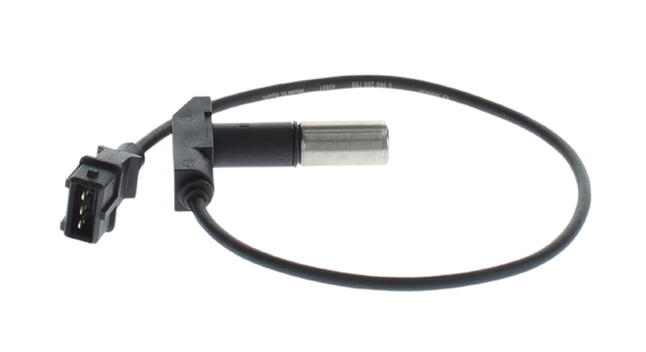
The Porsche 924S and 944 DME relies on two inductive sensors mounted at the top of the bell housing. Together they tell the engine management computer exactly where the engine is in its cycle.
They are among the first things to suspect when a 924S or 944 develops hard starting, intermittent stalling, or a tachometer that refuses to move during cranking.
What each sensor does
The reference sensor (marked B on the mounting bracket, labelled BG on the wiring harness) detects the top dead centre position of the number one piston on the compression stroke. The DME uses this signal as its fixed reference point.
The speed sensor (marked D on the bracket, labelled DG on the harness) counts the teeth on the flywheel ring gear and feeds the DME a continuous stream of pulses that it translates into engine RPM. It also acts as a safety switch: once the engine has started, the DME cuts the fuel pump if RPM drops below 300 stopping the pump from running if the engine stalls or the car is in an accident.
Used together, the two signals allow the DME to fire the injectors at exactly the right moment throughout the engine cycle.
Locating the sensors
Both sensors sit in a common bracket at the top of the bell housing, at the rear of the engine. From the driver's side of the car, look down behind the intake manifold toward the firewall. The bracket bolts to the bell housing and faces the ring gear on the flywheel. The reference sensor is the one closest to the engine block; the speed sensor sits behind it, closer to the firewall.
Tools needed
- 5 mm Allen head socket or 10 mm socket (sensor retaining bolts two types were used depending on the year)
- 6 mm Allen head socket (bracket locking bolt)
- 0.8 mm thick washer (for clearance adjustment only)
- Digital multimeter
- Oscilloscope (optional for a definitive output signal check)
Testing the sensors
Resistance check
A resistance check with a multimeter tells you whether the sensor coil is intact. Start by disconnecting the combined sensor connector at the back of the engine compartment, then take readings at the DME plug.
| Sensor | Terminals | Expected reading |
|---|---|---|
| Speed | 8 – 27 | 600 – 1600 Ω |
| Speed | 8 – 23 | > 1 MΩ |
| Reference | 25 – 26 | 600 – 1600 Ω |
| Reference | 25 – 78 | > 1 MΩ |
A reading outside these ranges too low, too high, or open circuit points to a failed sensor. A reading within range confirms the coil is healthy, but does not guarantee the sensor is producing a usable output signal at cranking speed.
Output signal check
The most reliable way to verify the sensors are actually working is to check their output with an oscilloscope while the engine is being cranked.
Before testing: remove the fuel pump fuse and disconnect the DME plug.
- For the speed sensor, connect the oscilloscope between terminals 8 and 27. Crank the engine and look for a sawtooth waveform with a peak-to-peak voltage above 2.5 V.
- For the reference sensor, connect between terminals 25 and 26. Crank the engine and look for a periodic pulse above 2.0 V peak-to-peak.
If the voltage is below spec, the sensor clearance is likely too large see the adjustment section below before replacing the sensor.
A multimeter can be used instead of an oscilloscope if you do not have one: it will confirm whether a signal is present at all, but it cannot measure the magnitude reliably. Treat a multimeter output test as indicative only.
Quick check without instruments
Crank the engine and watch the tachometer. If the needle jumps even briefly the sensors are producing a signal. If the needle stays flat, you have a problem with one or both sensors, their clearance, or the DME itself.
Removing the sensors
- Disconnect the battery negative lead.
- Unplug the speed and reference sensor connectors at the back of the engine compartment.
- Remove the sensor retaining bolt 5 mm Allen head or 10 mm socket depending on the version fitted.
- Twist the sensor gently from side to side as you pull up. After years on the car they can seize in the bracket; the twisting motion breaks the grip without damaging the sensor body.
Installing the sensors
If you are replacing both sensors at the same time, make sure you put each one back in the right hole. The wiring harness connectors are labelled near the connector bracket:
- DG = speed sensor
- BG = reference sensor
The mounting bracket is marked in the same way:
- D = speed sensor location
- B = reference sensor location
If the marks on the bracket are worn or illegible: the speed sensor always goes in the position closest to the firewall.
If the wiring harness labels have been removed or the connectors are off their bracket, use resistance readings from the DME plug to trace which connector goes to which sensor.
Torque the retaining bolts to 8 Nm (6 ft-lb).
Adjusting sensor clearance
The sensors do not normally need adjustment after a straight swap. Clearance only needs to be set if the mounting bracket has been removed from the bell housing, or if the bracket locking bolt was accidentally loosened.
- Remove the speed sensor.
- Loosen the bracket locking bolt (6 mm Allen) and the pivot bolt, then re-tighten both finger-tight.
- Glue the 0.8 mm washer to the bottom of the speed sensor. This washer acts as a precise spacer some workshops keep a dedicated adjustment sensor with the washer permanently bonded to it.
- Install the sensor with the washer and tighten the retaining bolt.
- Push the bracket down until it stops against the ring gear on the flywheel.
- Tighten the bracket locking bolt and pivot bolt.
- Remove the sensor. If the sensor is going back in service, carefully pry the washer off.
- Reinstall the sensor and torque to 8 Nm.
- Reconnect the battery.
Going further
If you want to understand which version of the sensor bracket is fitted to your car and what changed between the 1982 original and the final 1991 design the article Porsche 924S & 944 TDC sensor bracket evolution covers all three generations in detail.
For a broader overview of the most useful maintenance and reliability work on these cars, see 5 affordable modifications for Porsche 924S/944.